• PART 1: DWG to KML, DEM Elevation Extraction & CSV Export
• PART 2: Alignments, Profiles & Custom Data Bands
• • PART 3: Canal Assembly, Corridor, Cross-Sections & Total Volume Table (Current)
• PART 4: Template Setup & A3 Sheet Layouts
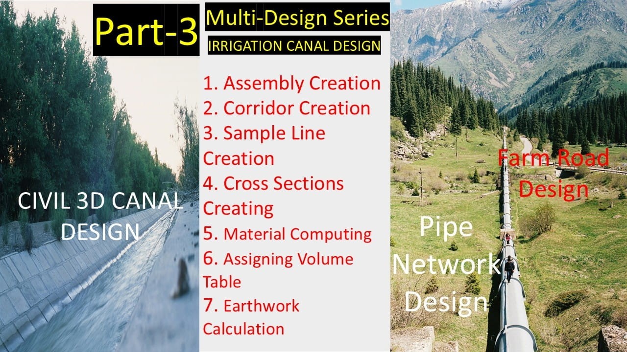
Welcome to Part 3 of our comprehensive Irrigation Design Masterclass. In this detailed tutorial, we take our design alignments and vertical profiles and transition into full 3D modeling—building custom canal cross-sections, generating corridors, setting target parameters, cutting sample lines, calculating cut-and-fill material quantities, and formatting professional earthwork volume tables.
1. Creating Custom Canal Cross-Section Assemblies
The assembly acts as the characteristic template for your canal structure that will be extruded along your horizontal alignment and vertical profile.
- Initialize Assembly Object: Navigate to the Home tab > Create Design > Assembly. Name your assembly (e.g.,
Main Canal Assembly) and place the baseline marker cleanly in your drawing view. - Attach Canal Components: Open the Tool Palette (Ctrl+3), select appropriate subassemblies such as
LinkWidthAndSlopeor specialized canal lining components, and attach them symmetrically to both the left and right sides of the baseline. - Configure Dimensions: Define precise geometric parameters for your canal bed width, side slope ratios (e.g., 1:1.5), lining thickness, and crest widths based on your hydraulic design calculations.

2. Adding Daylight Subassemblies for Embankment Grading
To tie your canal structure smoothly into the natural ground surface (OGL) at varying cut-and-fill depths, you must incorporate daylight links.
- Attach Daylight Links: From the tool palette, attach a
DaylightStandardorDaylightMaxWidthsubassembly to the outer edges of your canal banks or service roads. - Define Slope Parameters: Set the cut slope ratio (e.g., 1:1 for rock or compacted earth) and fill slope ratio (e.g., 1:2 for embankments) to ensure structural stability and compliance with site grading standards.
3. Generating the 3D Canal Corridor Model
Once your alignment, vertical design profile, and assembly template are complete, you can generate the parametric 3D corridor.
- Launch Corridor Creation: Go to the Home tab > Create Design > Corridor. Name the corridor and select your main canal alignment, design profile, and newly created assembly.
- Assign Target Surface: Set your existing ground TIN surface (e.g.,
OGL) as the target surface so the corridor knows when to transition between cut and fill. - Build Corridor: Click OK to generate the 3D solid model, establishing dynamic links across your entire canal length.

4. Configuring Corridor Frequency & Target Controls
Refining how your corridor samples terrain and interacts with boundaries ensures accuracy along sharp curves and elevation changes.
- Adjust Sampling Frequencies: Right-click your corridor, select Corridor Properties, and go to the Parameters tab. Click Frequencies to tighten sample intervals along curves (e.g., every 2 m to 5 m) and tangents (e.g., every 10 m) for smooth geometry.
- Manage Target Mappings: Use the Set Targets dialog box to map width or offset targets if your canal widening or bund paths need to follow specific boundary polylines.
5. Cutting Sample Lines along the Alignment
To analyze cross-sectional geometry and compute earthwork volumes, you must extract sample lines perpendicular to your alignment at regular stations.
- Initialize Sample Lines: Navigate to the Home tab > Profile & Section Views > Sample Lines. Select your main canal alignment.
- Define Swath Widths: In the Sample Line Tools toolbar, specify left and right swath widths (e.g., 25 m to 50 m on each side) wide enough to capture all corridor grading and natural terrain.
- Configure Sampling Increments: Set sampling intervals along tangents, major stations, and at critical geometric points (beginning and end of curves) to maintain high computation precision.
6. Computing Earthwork Cut-and-Fill Materials
With your sample lines established, Civil 3D can calculate the exact volumetric differences between your finished corridor design and the natural ground surface.
- Open Material Computation: Go to the Analyze tab > Compute Materials. Select your alignment and sample line group.
- Assign Criteria: Choose the standard Earthwork criteria file, mapping your existing ground surface as the EG reference and your corridor datum/top surfaces as the finished structure links.
- Execute Calculation: Click OK to process the volume calculations, generating cut, fill, and net volume data across every station.
7. Generating Cross-Section Views & Total Volume Tables
The final step packages your cross-sectional data and quantities into clear, presentation-grade tables for contractor review.
- Create Multiple Section Views: Navigate to the Home tab > Profile & Section Views > Section Views > Create Multiple Views. Choose your sheet layout settings, scale, and group plot style.
- Place Section Grids: Click in your drawing area to generate the grid sheets showing your canal assembly nested inside the natural ground profile.
- Insert Total Volume Takeoff Table: Go to the Analyze tab > Volume Tables > Total Volume, select your material list, and place the final quantity table directly into your drawing sheets to summarize total cut, fill, and structural volume.

Watch the full step-by-step visual demonstration here: Master Civil 3D: Canal Assembly, Corridor, Cross-Sections & Total Volume Table (Part 3).


0 Comments
Please read like, share and comment